Recently I came across an implementation task to provide a process to build a Window Wall System is Revit, once again I'm sure many of your will benefit from this post so read ahead. What I have to start off is an elevation of two bays that are 20'-00" in span. So let's beginning breaking this down. What I am showing you in this elevation is the complete system in addition to two very important datums objects; reference planes. To successfully assemble this system we will create two reference planes at predetermined heights based on our system design which we will use to anchor the bottom of our beam and windows too.
So to start I'm going to assume that we have columns evenly spaces every 20'-00" and that we have the first run of window already installed on the bottom level. So on elevation if our modules are 7'-6" high, I am going to create two reference planes. One of them will sit right on top of the already in place windows (7'-6") and will make sure that I name it so that I can use it as a drawing plane in the future. To do so, I will select the reference plane, pull up its Element Properties and insert a distinctive name (in this case MID BEAM - WWS) into the instance parameter Name.
 Once the plane in named it should like this when selected. Keep in mind the name will once show when the Ref. Plane is selected. Let's repeat the process now for a second Ref. Plane, We will use this plane to draw our second row of windows resting on the beam, therefore I will create this Ref. Plane 10" from the previous one which is the height of my beam. I will call this Ref. Plane TOB - WWS.
 One this is all in place we can now go to a floor plan, I chose Level 1. Since we already have the bottom window section and the default view range has a cut plane of 4'-00", we will now move the cut place so that we can see above the beam we are about place and the windows for the upper windows. To do this we will pull up the view property window and click on VIEW RANGE. Since we want to move the cut plane up and in a way eliminate what is bellow us we will make the following changes to the Primary Range: I have changed the Cut plane from 4' to 8' (remember the the bottom of the beam is at 7'-6") - I also mentioned I was not interested in seeing the objects close the ground so I change the Bottom Offset to 6' from its default of 0'-00" This means you have a view of Level 1 between 6' and 8'.
 This more or less how your view should look:
 At this point we need to select the first Ref. Plane we created to that we can lay our beam on top of it. In order to to that we need to click the Plane button located on the upper tool bar, this button will then bring up a context dialog for us to choose the Ref. Plane.

 Make sure you select the Name option and from the pull down you select MID BEAM - WWS which is the name of our first Ref. Plane. From this point on any object inserted into the view will be aligned on top of this Ref. Plane. From the Structural tool panel we are going to plane a Beam between the columns, what is most important about this part of the exercise is to set the beam properties for Z Direction Justification to Bottom. You can do this before or after you place the beam. Other parameters to look at include Start and End Justification, set these to zero.
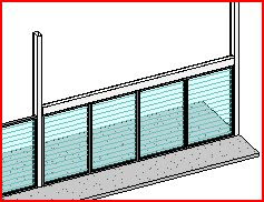
Now that we have the beam in place as show above, we can select the second Ref. Place by clicking on the Plane button on the top most tool bar and going through the same procedure. However this time when you extend the drop down menu make sure you select the Ref. Plane TOB - WWS and use this plane to insert the second row of windows.


