I am happy to announce that our mentoring and product knowledge has allowed one of the top Architectural firms in the world to complete their design development drawings in Revit 100% last week!
Just so you know, this is a project that is employing collaboration from Structural and Mechanical engineers. The most interesting fact is that they are all in remote locations and using their respective "flavor" of Revit to contribute to this project. At the moment I can not disclose any more specifics, but I will soon post more information on how Revit has helped the Architect and Consultants get the job done effectively !
Sign up for Basic training, and get more done in less time and more effectively with Revit ! Once you have mastered the basics, let's get together for discussion on more advanced topics.
For more information shoot me an e-mail crullier@ddscad.com, mention this blog posting and receive 100 dollars off your first training ;)
Sunday, March 2, 2008
Thursday, February 21, 2008
I can't see my rooms...
As you know, when you delete the room tags from you floor plan doesn't necessarily mean you deleted the room objects; They are still there. However, often you will find yourself inserting a room object into a space that already has a room. So here is a little trick - enable the visibility for the room reference lines and color fill.


Thursday, February 14, 2008
Happy Valentines - Revit Heart Wall
Happy Valentines Day everyone, I thought it would be a good idea to use the ocassion to remind of the Edit Sketch function within the wall object. While very basic, it's been handy many times.

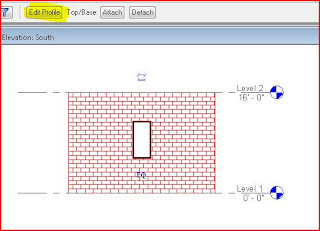




To begin you need to have a wall selected in elevation. Once the wall is selected you will see in the options bar an option to Edit Sketch.

When you click on it, you will go into an overlay mode which is know as sketch more. This overlay mode allow you to change the elevation qualities of the selected wall, this is achieved by either modifying the existing four lines (top, bottom, left or right) or in this car by creating new ones using the Lines command from the Sketch mode tool bar on the left.


Once you are happy with the new elevation shape of your wall, you can click Finish Sketch, or Quit Sketch if you're not (howeve please know the if you Quick Sketch, you can not undo !)

Now you should see that the original wall has taken a new shape, derived from the lines you drew. If any point you wish to change the shape of the all, or even the remove the siluete overide, you can select the wall and look at the option bar where you will find two options. Edit Profile - lets you make changes, or Remove Sketch - revert the profile back to its original state, ortogonal.

Enjoy the day !
Monday, February 11, 2008
Tapered Slab Edges
Hello again ! What I want to share how to take a regular slab in Revit Architecture and taper any or all of its edges. In order to do this we need we will use "The Floor Slab Edge" tool found under "Host Sweep" in the Modeling tool drawer and click on the edges on the floor slab we want to alter. However before we begin we need to configure the "Edge" and this is the tricky part.
First let's build a profile which will give us the shape of the taper. Lets go to and on the dialog box, let's select the appropriate templeter which is Porfile.rtf and click open.

What we have now in front is a drawing area in which we are going to draw our 2D profile. Since this profile will be swept around the edges of the floor slab, we need to draw a section of the taper we want to occur.

Use the Line tool to draw the shape and you can use refereance planes if you wanted to make the profile parametric. By the way come to one of our cusomized training to learn how to build parametric components.

Now just save the profile and load it into your current project or into the project were the floor slab you wish you modify exist or will be created. Now we can go into and redefine the existing slab edge to use the profile we just created.

Once the element properties dialog appear, we need to either rename the current Slab Edge definiton or create a new one by using the Element properties dialog and into Type porperties.

At this point as you can see in the above screen shot, all you need to do is load the profile we made, click OK to exit all the dialogs and beging to click on the edges of your Floor object.
e-mail me or call me here at the office if you have any questions.
Wednesday, January 9, 2008
Bug Alert - Unspecified error when saving groups.
Happy new year everyone !
I would like to share something with you that was recently brought to my attention by Autodesk Support. There seems to be a bug within Revit which during the month of January 2008 will not allow you to save groups, instead during this process you will receive an error: “Unspecified error”.

However, once we move into February and through the rest of 2008 this issue will no longer affect us.

The way to work around it however, is to change the month (date) within Windows to a month other than January 2008. Your choice could be a month in the past or in the future; however keep in mind that if you have any outlook reminders these will be affected and they flash on your screen - so be careful!!! Once you are finished saving your groups you can reset your date settings.

I would like to share something with you that was recently brought to my attention by Autodesk Support. There seems to be a bug within Revit which during the month of January 2008 will not allow you to save groups, instead during this process you will receive an error: “Unspecified error”.

However, once we move into February and through the rest of 2008 this issue will no longer affect us.

The way to work around it however, is to change the month (date) within Windows to a month other than January 2008. Your choice could be a month in the past or in the future; however keep in mind that if you have any outlook reminders these will be affected and they flash on your screen - so be careful!!! Once you are finished saving your groups you can reset your date settings.

Monday, December 10, 2007
A Window Wall System - Scratching the Surface
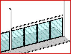
Recently I came across an implementation task to provide a process to build a Window Wall System is Revit, once again I'm sure many of your will benefit from this post so read ahead. What I have to start off is an elevation of two bays that are 20'-00" in span. So let's beginning breaking this down.

What I am showing you in this elevation is the complete system in addition to two very important datums objects; reference planes. To successfully assemble this system we will create two reference planes at predetermined heights based on our system design which we will use to anchor the bottom of our beam and windows too.
So to start I'm going to assume that we have columns evenly spaces every 20'-00" and that we have the first run of window already installed on the bottom level. So on elevation if our modules are 7'-6" high, I am going to create two reference planes. One of them will sit right on top of the already in place windows (7'-6") and will make sure that I name it so that I can use it as a drawing plane in the future. To do so, I will select the reference plane, pull up its Element Properties and insert a distinctive name (in this case MID BEAM - WWS) into the instance parameter Name.

Once the plane in named it should like this when selected. Keep in mind the name will once show when the Ref. Plane is selected. Let's repeat the process now for a second Ref. Plane, We will use this plane to draw our second row of windows resting on the beam, therefore I will create this Ref. Plane 10" from the previous one which is the height of my beam. I will call this Ref. Plane TOB - WWS.

One this is all in place we can now go to a floor plan, I chose Level 1. Since we already have the bottom window section and the default view range has a cut plane of 4'-00", we will now move the cut place so that we can see above the beam we are about place and the windows for the upper windows. To do this we will pull up the view property window and click on VIEW RANGE.
Since we want to move the cut plane up and in a way eliminate what is bellow us we will make the following changes to the Primary Range: I have changed the Cut plane from 4' to 8' (remember the the bottom of the beam is at 7'-6") - I also mentioned I was not interested in seeing the objects close the ground so I change the Bottom Offset to 6' from its default of 0'-00" This means you have a view of Level 1 between 6' and 8'.

This more or less how your view should look:

At this point we need to select the first Ref. Plane we created to that we can lay our beam on top of it. In order to to that we need to click the Plane button located on the upper tool bar, this button will then bring up a context dialog for us to choose the Ref. Plane.


Make sure you select the Name option and from the pull down you select MID BEAM - WWS which is the name of our first Ref. Plane. From this point on any object inserted into the view will be aligned on top of this Ref. Plane. From the Structural tool panel we are going to plane a Beam between the columns, what is most important about this part of the exercise is to set the beam properties for Z Direction Justification to Bottom. You can do this before or after you place the beam. Other parameters to look at include Start and End Justification, set these to zero.



What I am showing you in this elevation is the complete system in addition to two very important datums objects; reference planes. To successfully assemble this system we will create two reference planes at predetermined heights based on our system design which we will use to anchor the bottom of our beam and windows too.
So to start I'm going to assume that we have columns evenly spaces every 20'-00" and that we have the first run of window already installed on the bottom level. So on elevation if our modules are 7'-6" high, I am going to create two reference planes. One of them will sit right on top of the already in place windows (7'-6") and will make sure that I name it so that I can use it as a drawing plane in the future. To do so, I will select the reference plane, pull up its Element Properties and insert a distinctive name (in this case MID BEAM - WWS) into the instance parameter Name.

Once the plane in named it should like this when selected. Keep in mind the name will once show when the Ref. Plane is selected. Let's repeat the process now for a second Ref. Plane, We will use this plane to draw our second row of windows resting on the beam, therefore I will create this Ref. Plane 10" from the previous one which is the height of my beam. I will call this Ref. Plane TOB - WWS.


One this is all in place we can now go to a floor plan, I chose Level 1. Since we already have the bottom window section and the default view range has a cut plane of 4'-00", we will now move the cut place so that we can see above the beam we are about place and the windows for the upper windows. To do this we will pull up the view property window and click on VIEW RANGE.
Since we want to move the cut plane up and in a way eliminate what is bellow us we will make the following changes to the Primary Range: I have changed the Cut plane from 4' to 8' (remember the the bottom of the beam is at 7'-6") - I also mentioned I was not interested in seeing the objects close the ground so I change the Bottom Offset to 6' from its default of 0'-00" This means you have a view of Level 1 between 6' and 8'.

This more or less how your view should look:

At this point we need to select the first Ref. Plane we created to that we can lay our beam on top of it. In order to to that we need to click the Plane button located on the upper tool bar, this button will then bring up a context dialog for us to choose the Ref. Plane.


Make sure you select the Name option and from the pull down you select MID BEAM - WWS which is the name of our first Ref. Plane. From this point on any object inserted into the view will be aligned on top of this Ref. Plane. From the Structural tool panel we are going to plane a Beam between the columns, what is most important about this part of the exercise is to set the beam properties for Z Direction Justification to Bottom. You can do this before or after you place the beam. Other parameters to look at include Start and End Justification, set these to zero.


Now that we have the beam in place as show above, we can select the second Ref. Place by clicking on the Plane button on the top most tool bar and going through the same procedure. However this time when you extend the drop down menu make sure you select the Ref. Plane TOB - WWS and use this plane to insert the second row of windows.

Saturday, December 8, 2007
Keeping File Size to a Minimum !!
I wanted to share something I recently learned. Revit files automatically get compressed when the SAVE AS option is used to save your project rather than just the conventional SAVE. This is how is works, take for intance the following file ROOF FRAMING_MODEL.rvt its normal size is 5,080 K. However if I use the SAVE AS function and give this file a new name such as ROOF FRAMING_MODEL_SAVE AS.rvt you will notice that the file size decreased to 4,440K. This is almost 15% smaller. At this point you can then delete you original file and replace it with the new one.
Original File:

Save As File:

Original File:

Save As File:

Subscribe to:
Posts (Atom)